Design A Combinational Circuit For 4 Bit Binary Subtractor
4 Bit Binary Adder Subtractor Geeksforgeeks

Binary Subtractor Used For Binary Subtraction
Binary Adder Subtractor Combinational Logic Circuits Electronics Tutorial
Solved Using Four Half Adders Design A Four Bit Combinat Chegg Com
Binary Adder And Subtractor
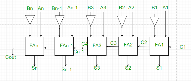
Parallel Adder And Parallel Subtractor Geeksforgeeks

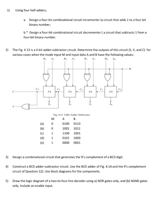
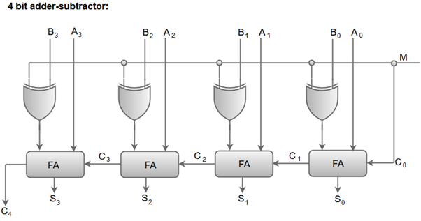
The circuit has a mode input bit m that controls its operation.
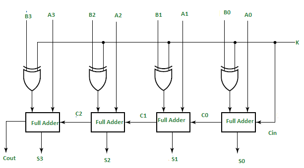
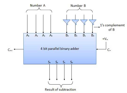
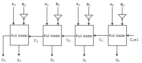
Design a combinational circuit for 4 bit binary subtractor. When the subtraction input is logic 0 the b3 b2 b1 b0 are passed to the full adders. A0 a1 a2 a3 for a b0 b1 b2 b3 for b. However to add more than one bit of data in length a parallel adder is used. Half subtractor is the most essential combinational logic circuit which is used in digital electronics basically this is an electronic device or in other terms we can say it as a logic circuit.
In this subtraction of the two digits is performed by taking into consideration whether a 1 has already borrowed by the previous adjacent lower minuend bit or not. A full adder adds two 1 bits and a carry to give an output. You may use one s or two s compliment of b to perform subtraction. Figure above the realization of 4 bit adder subtractor.
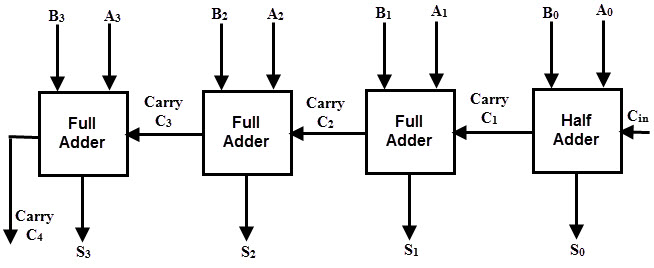
This circuit requires prerequisite knowledge of exor gate binary addition and subtraction full adder. Design a 4 bit adder subtractor circuit using the 4 bit binary full adders 74ls83 and any necessary additional logic gates. Half subtractor is used to perform two binary digits subtraction. A parallel adder is an arithmetic combinational logic circuit that is used to add more than one bit of data simultaneously.
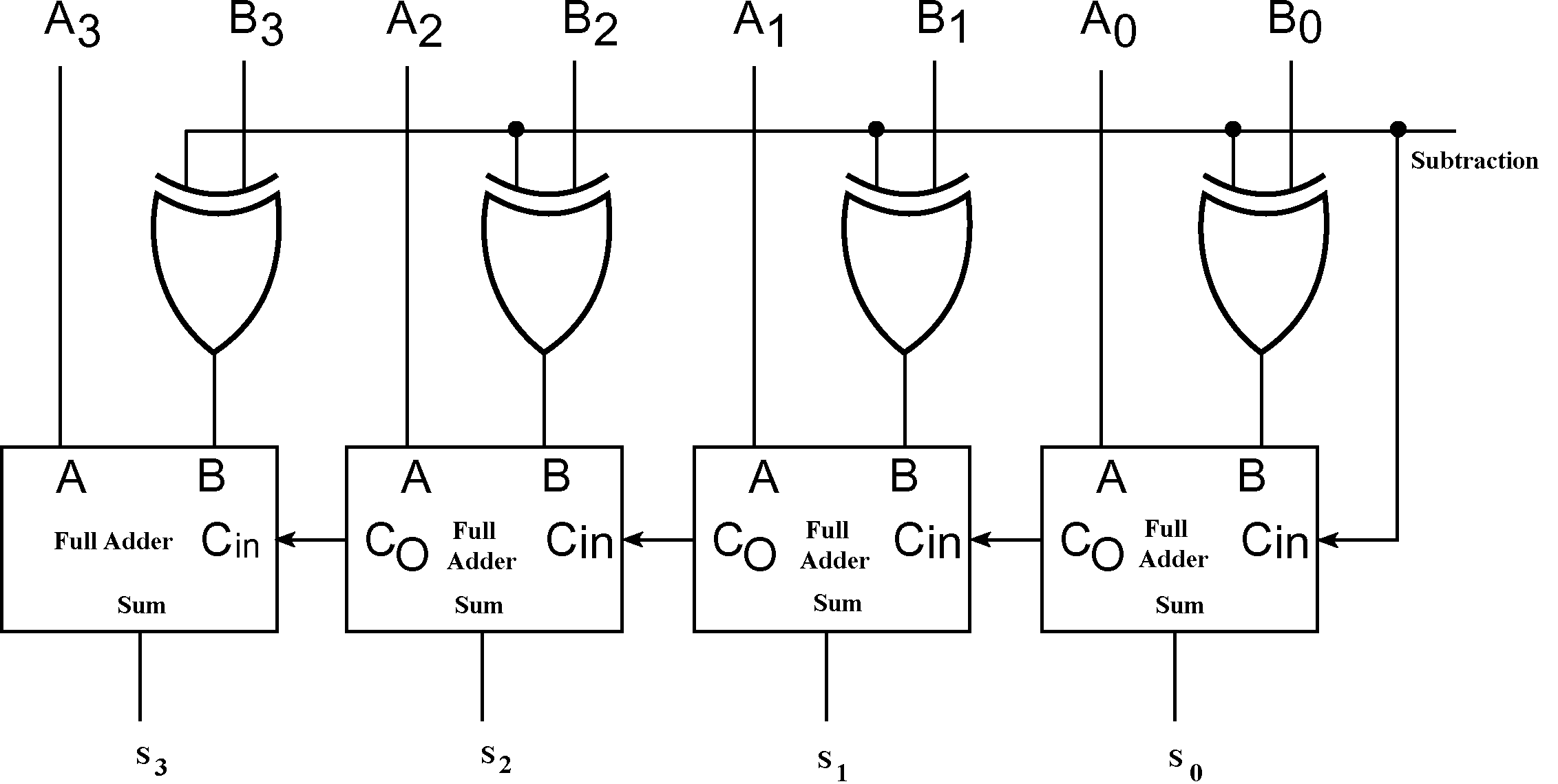
The result with the proper sign is to be displayed in un complemented binary form. The control input is controls the addition or subtraction operation. Specifically when m 0 the circuit becomes a 4 bit adder and when m 1 the circuit becomes a 4 bit subtractor that performs the operation a plus the 2 s complement. Given two 4 bit positive binary numbers a and b you are to design an adder subtractor circuit to compute a b or a b depending upon a mode input which controls the operation.
The circuit consists of 4 full adders since we are performing operation on 4 bit numbers. From the figure it can be seen that the bits of the binary numbers are given to full adder through the xor gates. A combinational logic circuit performs a subtraction between the two binary bits by considering borrow of the lower significant stage is called as the full subtractor. The half subtractor is a combinational circuit which is used to perform subtraction of two bits.
Combinational Circuits Tutorialspoint
Digital Arithmetic Circuits Tutorialspoint

Binary Adder And Binary Addition Using Ex Or Gates
Coa Binary Adder Subtractor Javatpoint

Chapter 4 Homework V3 Solutions Ens 221 Csi Studocu
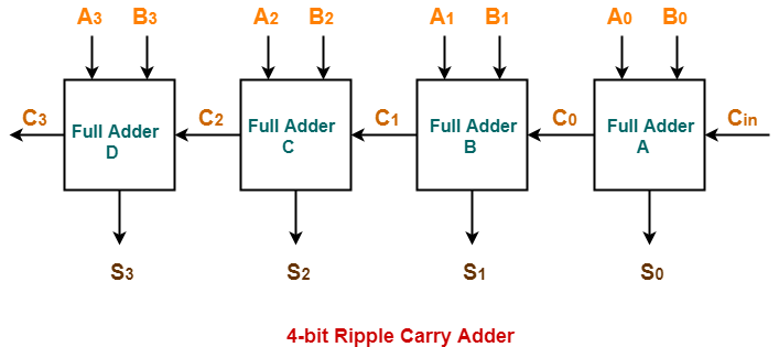
Ripple Carry Adder 4 Bit Ripple Carry Adder Gate Vidyalay
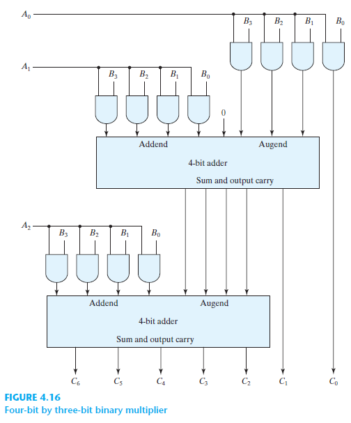
Solved For A Binary Multiplier That Multiplies Two Unsigned Fo Chegg Com

Cs201 Design Adders Lab

Q 4 11 Using Four Half Adders Hdl See Problem 4 54 A Design A Full Subtractor Circuit Incremen Youtube
4 10 Design A Four Bit Combinational Circuit 2 S Complementer The Output Generates The 2 S Youtube

What Is The Logic Diagram Of 4 Bit Subtractor Quora
Morris Mano Edition 3 Exercise 5 Question 3 Page No 197 Gate Overflow
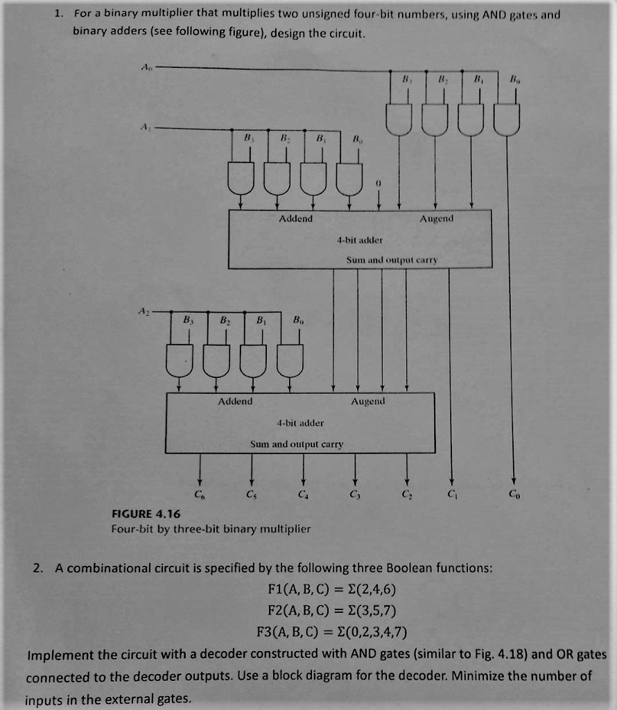
Solved 1 For A Binary Multiplier That Multiplies Two Uns Chegg Com

