Design A Combinational Circuit With Three Inputs And Three Outputs

Q 4 5 Design A Combinational Circuit With Three Inputs X Y And Z And Three Outputs A B And C Youtube
Https Ece Uwaterloo Ca Msachdev Ece223 Assignment4 Solution 3rd Edition Pdf

Lecture 13 Problems Mano Ppt Video Online Download

Pin On Digital Logic Circuits

Design Of Parallel Adder In 2020 Binary Number Parallel Simple Solutions

Combinational Circuits Circuit Electronics Circuit Block Diagram

When the binary input is 0 1 2 or 3 the binary output is 1 greater than the input.
Design a combinational circuit with three inputs and three outputs. 4 5 design a combinational circuit with three inputs x y and z and three outputs a b and c. When the binary input is 4 5 6 or 7 the binary output is three less than the input. When the binary input is 0 1 2 or 3 the binary out. When the binary input is 4 5 6 or 7 the binary output is one less than the input.
Design a combinational circuit with three inputs x y z and three outputs a b and c. Specifically x should be true if the number is divisible by 3. Design a combinational circuit with 4 inputs a3 a2 a1 a0. When the binary input formed from xyz is 0 1 2 or 3 the binary output produced by abc is.
The half adder circuit is designed to add two single bit binary number a and b. And z should be true if the number is a. And three outputs x y z. The inputs represent a binary number in the range 0 15 and the outputs represent characteristics of the numbers.
Y should be true if the number is prime. When the binary input is 4 5 6 or 7 the binary output is one less than the input. Half adder is a combinational logic circuit with two inputs and two outputs. A combinational circuit can have an n number of inputs and m number of outputs.
Follow the above listed points to design the logic diagram as per the given statement. Eg 2 10 3 10 5 10 7 10. Design a combinational circuit with three inputs x y and z and three outputs a b and c. When the binary input is 0 1 2 or 3 the binary output is one greater than the input.
Design a combinational logic circuit with three input variables such that it will produce logic 1 output when one or two the input variables are logic 1 but not all the three. Example of combinational logic circuit. Design a combinational circuit with three inputs x y and z and three outputs a b and c. Design a combinational circuit with three inputs x y and z and three outputs a b and c.
When the binary input is 0 1 2 or 3 the binary output is two greater than the input. Given two input bits a and b produce three outputs x y and z so that x is 1 only when only when a b y is 1 only when a b and z is 1 only when a b learn more. We re going to elaborate few important combinational circuits as follows. When the binary input is 0 1 2 or 3 the binary output is one greater than the input.
When the binary input is 4 5 6 or 7 the binary output is one less than the input.
Http Site Iugaza Edu Ps Aaldali Files 2015 01 Dd Assignment 2 Solution Pdf
Combinational Logic

Pin On Electronic Schematics
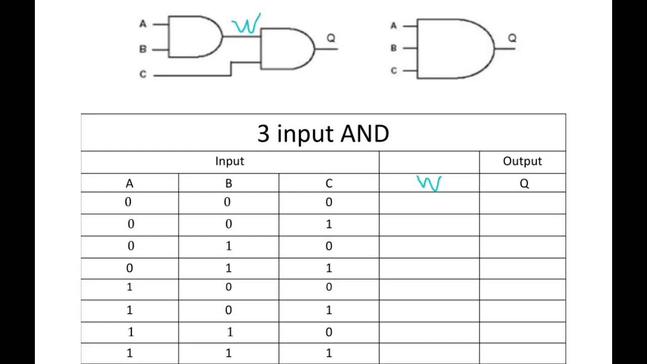
3 Input And Gate Truth Table Worked Out Youtube

2 Bit Synchronous Up Counter Electronics Circuit Circuit Digital

Unijunction Transistor Ujt Equivalent Model Circuit Electronics Area Transistors Circuit Electronics Components

Pin On Mrmgate

Simulation Of A Half Adder Circuit With 4 Basic Gates Using Tina Circuit Design Simulation Circuit Simulator

4 Bit Parallel Subtractor Parallel Logic Design

Power Supply For Audio Amplifier Circuit Multiple Output 12v 15v 35v Audio Amplifier Power Supply Circuit Basic Electronic Circuits

3 Bit Synchronous Up Down Counter Electronics Circuit Counter Circuit

Arduino Lcd With Tinkercad Wires Arduino Arduino Lcd Arduino Projects

Connection Of Potentiometer Google Search Resistors Voltage Divider Circuit

