Design A Combinational Circuit That Generates Output As 1

1 Bit Comparator Logic Electronics Circuit Bits

Combinational Logic Logic Electronic Engineering Circuit
Https Ece Uwaterloo Ca Msachdev Ece223 Assignment4 Solution 3rd Edition Pdf

3 Bit Synchronous Up Down Counter Electronics Circuit Counter Circuit
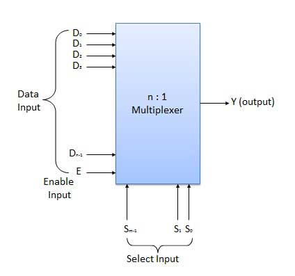
Combinational Circuits Tutorialspoint
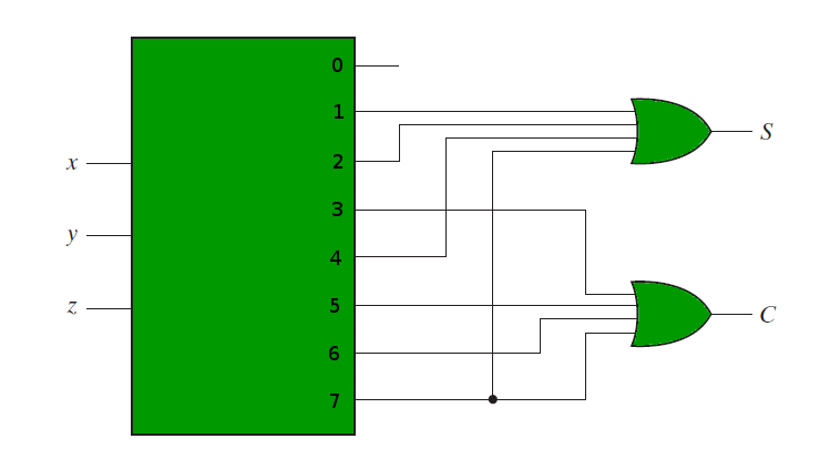
Combinational Circuits Using Decoder Geeksforgeeks

A parity generator is a combinational logic circuit that generates the parity bit in the transmitter.
Design a combinational circuit that generates output as 1. The circuit has 3 inputs as the octal digits need 3 bits to be represented where it would only take the octal digits. The output generates the 2 s complement of the input binary number show that the circuit can be constructed with exclusive or gates. The output would generate the even parity bit for the corresponding input given. Given two input bits a and b produce three outputs x y and z so that x is 1 only when only when a b y is 1 only when a b and z is 1 only when a b learn more.
Example of combinational logic circuit. Design a combinational logic circuit with three input variables such that it will produce logic 1 output when one or two the input variables are logic 1 but not all the three. Draw the truth table for a combinational circuit that generates output as 1 only for particular input pattern double the student s vtu number 14974 write the boolean expression in standard sop form design nand nand implementation nor nor implementation for that expression derived from i design a data selector circuit for that truth. Consider the three bit number a 2 a 1 and a 0 and generate the six bit binary number s 5 s4 s3 s2 s1 and s 0 output equal to the square of the input number the block diagram of this combinational circuit is given below.
Solution for design a 4bits combinational circuit 2 s complementer the output generates the 2 s complement of the input binary number. Since the square of 7 the highest possible number with 3 bits is 49 and this is bigger than 2 5 you would need to have 6 output functions. The combinational circuit do not use any memory. The previous state of input does not have any effect on the present state of the circuit.
The output of combinational circuit at any instant of time depends only on the levels present at input terminals. On the other hand a circuit that checks the parity in the receiver is called parity checker. You can of course realize these independently as functions of the 3 inp. Design a circuit that has a 3 bit binary input and a single output that output 1 if it is a prime number.
The answer of prem sobel is good. For example if the input is octal digit 2 i e in binary 010. Eg 2 10 3 10 5 10 7 10. A combinational circuit can have an n number of inputs and m number of outputs.
Follow the above listed points to design the logic diagram as per the given statement. Compare two 1 bit numbers.

What Is A Sequential Circuit Digital Electronics Electronics Area Circuit Digital Electronics
Http Web4 Uwindsor Ca Users A Alginahi 60 265 Nsf 831fc2c71873e46285256d6e006c367a 9391445fba4fc83f85256fc8004827a3 File Assignment3 Solutions 20265 Pdf

Sequential Logic Circuits Circuit Digital Circuit Logic

4 1 Annotated Slides 4 Combinational Logic Computation Structures Electrical Engineering And Computer Science Mit Opencourseware

Three Phase Sine Wave Generator Circuit Diagram Generates Three Sine Wave How To Generate Three Sine Waves Using Simlple Electronic Sine Wave Generation Waves

Hello Good Morning Friends Today A Small Circuit To Generate Sparks Using Igination Coil We Are Into Professional Electronics Circuit Design And Prototype Dev
Pin On Electronic Project Ideas

Logic Gate Control Systems 2 Output Device Logic Circuit

Drumcube An Arduino Robot Drummer Electronics Circuit Arduino Electronic Engineering

Combinational Logic Circuits Using Logic Gates

Logic And Gate Tutorial Truth Table Electronics Area Logic Tutorial Truth

High Voltage Dc Generator Circuit 12vdc Input 10 000vdc Output Electrical Enginee Electronic Circuit Projects Electronic Engineering Electronics Circuit

Op Amp Cookbook Part 3 Electronic Schematics Function Generator Electronics

